Three-phase full-wave controlled rectifier circuit with RLC Load on PSIM || Simulation of 3-phase
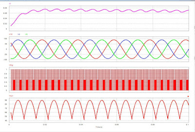
Introduction In this article, I’m going to tell you about a full wave-controlled rectifier with RLC Load . The word Controlled means the devices for power conversion are Known as controlled Rectifier . The input is AC and the output is DC . For designing a Ful l- Wave controlled Rectifier there is 6 SCR are required. I am using PSIM’s latest version for designing. My circuit is not hardware-based my design circuit is for power electronics practical. Power electronics is a subject that teaches in Engineering Universities. In Power Electronics we study the conversion, inversion, stepdown, step up, Cyclo-converter, Buck Converter, Boost Converter, Buck-Boost Converter. Working The working operation of this circuit is that two SCR is for a 120` (Redline) half cycle and two SCR is for the 120` (Yellow line) half-cycle and TWO SCR is for 120` (Blue line) half cycle . The load is the Resistor inductor and capacitor . The value...


